
You successfully your special valves sketches.
You will receive a confirmation email with your sketches.
For any further information, please contact us.
All data entered in this tool will now be deleted, so you can create new valves.
If you confirm, you will delete all entered data and you will start from the beginning!
Would you like to create another valve or continue and send those already created? Attention: if you continue you will no longer be able to edit your valves.
Steel S - UNI X45CrSi93
NOMINAL CHEMICAL COMPOSITION
C 0,45% - Si 2,9% - Mn 0,50% - Cr 9,0%
Widely used for intake valves, stems in bimetallic exhaust valve and valve stem tips in
internal combustion engines.
Steel N - UNI X53CrMnNiN21-9
NOMINAL CHEMICAL COMPOSITION
C 0,54% - Cr 21,00% - Mn 9,00% - Ni 4,00% - Si 0,20% - N 0,45%
Widely used for medium duty exhaust valves and heavy duty intake valves in both gasoline
and diesel engines. Maximum operating temperature is about 750°.
Steel H - UNI X50CrMnNiNbN21 9
NOMINAL CHEMICAL COMPOSITION
C 0,52% - Cr 21,00% - Mn 9% - Ni 4% - W 1% - N 0,5% - Nb 2%
Heavy duty exhaust valve, operating at temperatures up to about 780°C. Also used for highest
duty intake valves.
Alloy Y - Nimonic 80A - W. Nr. 2.4952 & 2.4631
C 0.10% max. - Cr 18.0/21.0% - Si 1.0% max - Cu 0.2% max. - Fe 3.0% max. - Mn 1.0% max. – Ti
1.8/2.7% – Al 1.0/1.8% Co 2.0% – Nickel Balance
NOMINAL CHEMICAL COMPOSITION
Special high performance super alloy having a nickel base, especially used for the production of engine valves operating under particular severe conditions (thermal and mechanical).
For his malleability Nimonic 80A is especially requested for applications where there is a risk of valve failure or breakage.
Nimonic 80 has excellent anti-corrosion properties
Bimetal valve
To meet different thermal and mechanical kind of stress, the valve head and the stem must sometimes have very different structural characteristics. For this reason are realized valves with two different materials (austenitic steel or Nimonic for the head and martensitic steel for the stem) joined together by friction welding. The part in contact with the distribution device is hardened, as well as (if necessary) also the area affected by the locking cotters.
Tip of stem with stellite
The STELLITE deposit on the tip of the valve is made on austenitic steels that cannot be hardened due to their technologic specifications. The purpose of this operation is to reduce the tip of the valve consumption during its contact to the involved distribution device.
Stellite welding
The STELLITE deposit on the SEAT of the valve is made to reduce oxidation and corrosion to a minimum. The addition of this cobalt-based alloy considerably increases the life of the valves forced to withstand high operating temperatures in a corrosive atmosphere. It is especially recommended for high performance or lead-free petrol, LPG and CNG engines.
CHROMIUM PLATING is a superficial treatment which consists in a uniform electrolytic deposit of chrome onto the stem of the valve. It assists operating conditions and increases wear resistance between the valve and the valve guide.

NITRIDING is a thermal total immersion in salt type bath, offering the valve extra antigrip and scuff properties. Nitriding is a surface hardening ensuring that the core of valve retains the original mechanical steel properties.

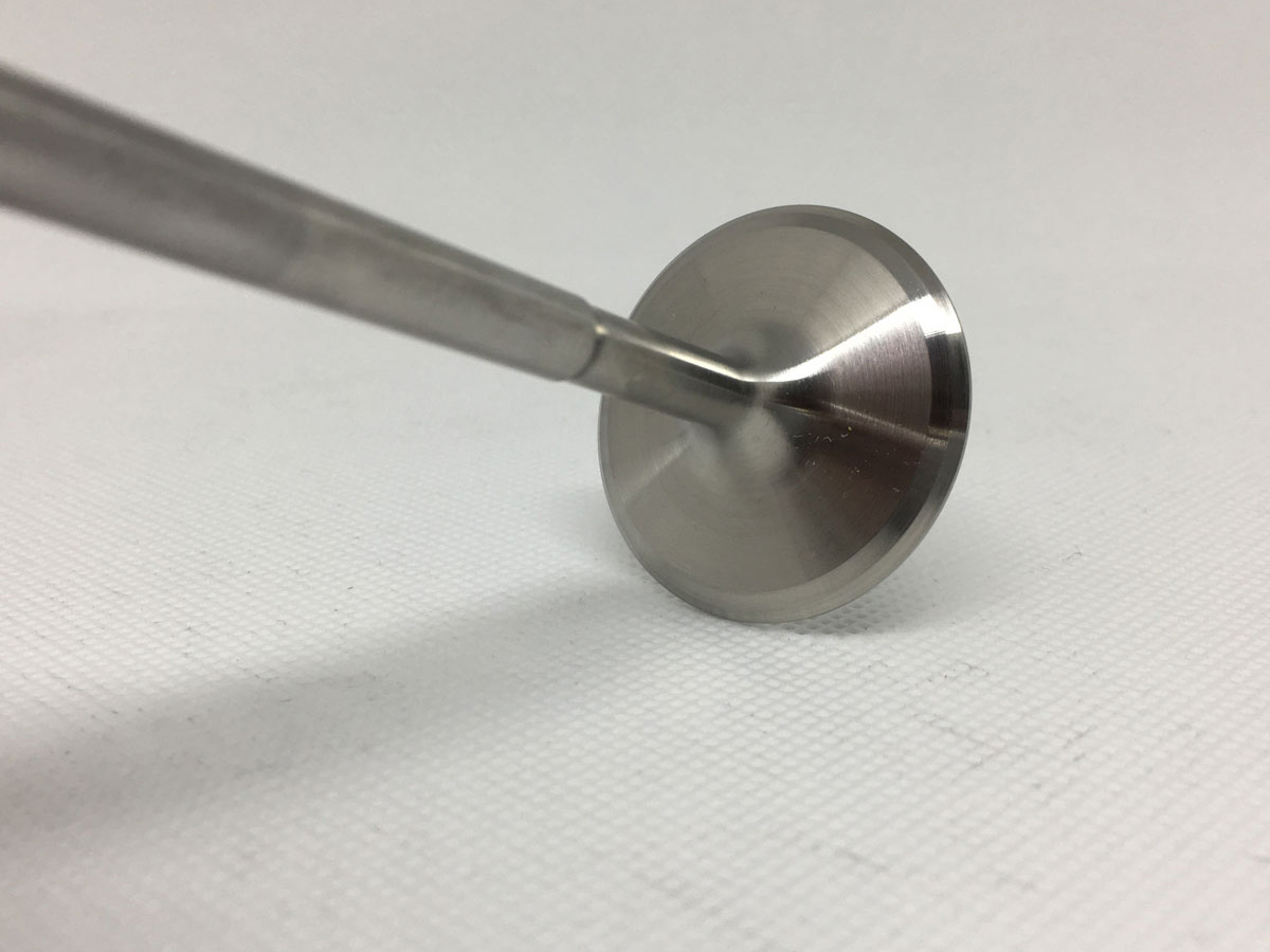
The valve head is polished with emery cloth in order to obtain a shiny surface and free from scratches caused by machining on machine tools.
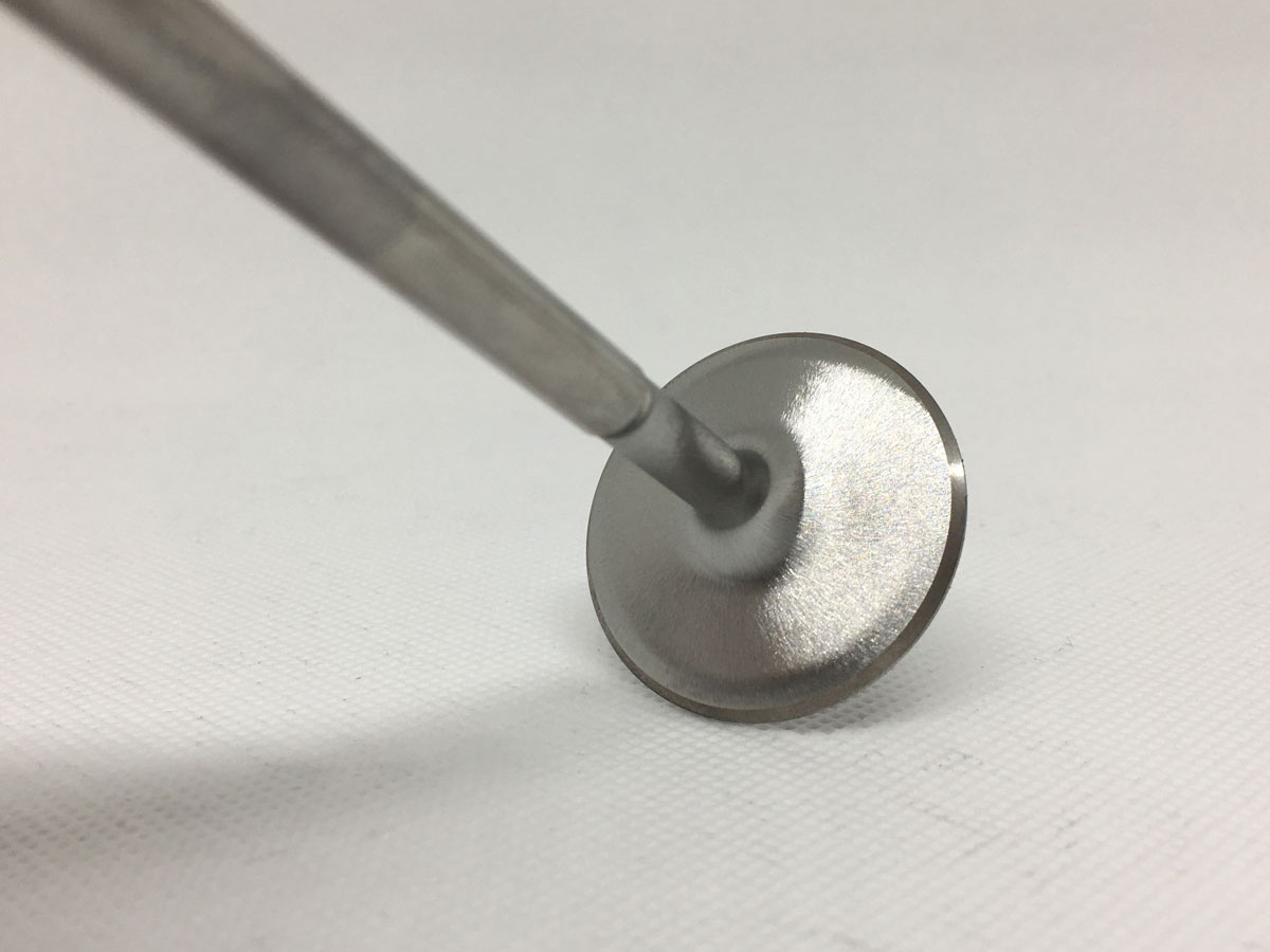
If requested by the customer, the internal part of the mushroom (throat) is processed with "Swirl polish" technology. This is a longitudinal sanding by emery cloth carried out with the valve rotating on its axis. In this way, all the transversal grooves are eliminated which, in extreme cases, could give rise to a breaking of the valve head. On the intake valves this processing also tends to generate the phenomenon of the "boundary layer" which, for fluid-dynamic reasons, contributes to facilitating the inlet flow.

We're sorry but your device is not compatible with our configurator.
Please visit us again on a desktop computer or laptop and try our revolutionary tool.
Carica i tuoi disegni! Clicca su Seleziona file per sceglierli e caricarli. Sono
supportati i file di formato: png, jpg, pdf, dxf, dwg. Puoi inviare al massimo 5
file dal peso massimo di 10MB ciascuno.


This valve will be used for: *
This valve will be used for: *
Please note that the quotation is indicative and is based only on the data provided.
We reserve the right to verify the congruence with the receipt of the complete sketch of the sample.